5. Scattering and
diffraction

In
the context of this chapter, you will also be invited to visit these
sections...
Electromagnetic radiations (such as
visible light) can interact among themselves and with matter, giving
rise
to a
multitude of phenomena such as reflection,
refraction,
scattering,
polarization...


Left:
Reflection and refraction of light in the
interface between glass
with a refractive index 1.5 and air with a refractive index
1.0. TIR = "Total Internal
Reflection"
Center: Refraction of light after passing
through
a glass prism. Depending on the wavelength (color) of the incident beam
(coming from the left), the angle of refraction varies, ie: it is
scattered
Right: Polarization of light passing
through a polarizer. Depending on the rotation of the polarizer, one of
components of the incident beam (coming from the right) is
filtered
Animations
originally taken from physics-animations.com
X-ray
diffraction is the physical phenomenon that expresses the fundamental
interaction between X-rays and crystals (ordered matter).
However, to describe the phenomenon it is advisable to first introduce
some physical models that (as all models) do not
fully explain reality (as they are an idealization of it), but
can be used to help understand the phenomenon.
On waves
A wave is
an undulatory phenomenon (a
disturbance) that propagates through space and time,
and is regularly repeated.
Waves are usually
represented graphically
by a sinusoidal
function (as
shown above), in which we can determine some general parameters that
define it.


Transverse wave propagation of vibrating
longitudinal and circular movements
Animations
originally taken from physics-animations.com
Undulatory phenomena
(waves) propagate at a certain speed (v) and
can be modeled to meet the so-called wave equation, scalar or
vectorial, depending on the nature of the disturbance. The solutions to
this equation are usually combinations of trigonometric terms,
each of them characterized by: 1) an amplitude
(A),
which measures the maximum (or minimum) of the disturbance
with
respect to an equilibrium value, and 2) a phase Φ:
Φ =
2π(K.r
- ν.t
+ α)
The intensity
of an undulatory disturbance, at any point of the wave, is proportional
to the square of the disturbance value at that point, and if it
is expressed in terms of complex exponentials, this is
equivalent to the product of the disturbance by its complex conjugate.
The intensity
is a measure of the energy flow per unit of time and per unit of area
of the wavefront (spherical or flat, depending on the type of wave).
A wave is a regular phenomenon, ie
it repeats exactly in time (with a period T)
and space (with a period λ,
the wavelength), so that λ
= ν.T,
or λ.ν=
v.
In the expression of the phase (Φ), K
is the so-called wave
vector which gives the sense of progress of the wave (the
ray), and is considered with an amplitude 1/λ.
Thus, K is
the number of repetitions per unit of length.
ν
is the frequency (the
inverse of the period),
that is, the number of repetitions (or cycles) per unit of time. We
give the name pulse
to the
magnitude given by: 2π.ν,
which
measures the number of repetitions per radian (180/π
degrees) of the cycle.
In the full electromagnetic
spectrum (ie in the distribution of electromagnetic
wavelengths) the hard
X-rays (the high energy ones) are located around a
wavelength of 1 Angstrom in vacuum (for Cu
the average wavelength is 1.5418 Angstrom and for Mo
it's 0.7107 Angstrom),
while visible
light has a wavelength in the range of 4000 to
7000 Angstrom.
t
and
r are,
respectively, the time and the position vector with which we measure
the
disturbance, and α
is the original phase
difference relative to the other components of the wave.
We speak of waves being in
phase if the difference between the phases of the
components is an integer multiple of 2π,
and we say that the waves are in opposition
of phase if that difference is an odd multiple of π.
For an easy mathematical treatment to keep track of the relations
between phases of the wave components, these terms are usually
expressed in an exponential notation, where the exponential imaginary
unit i
means a phase difference of +π/2.
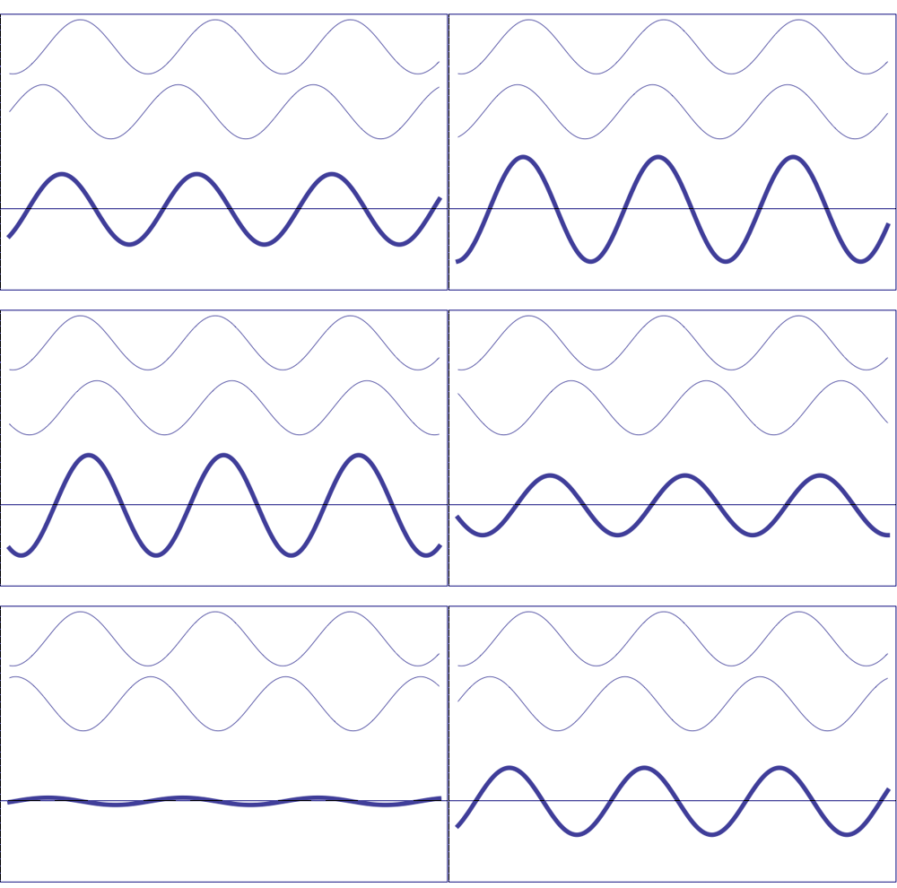
Possible states of interference of two
waves shown at the top, having identical amplitude and frequency. The wave drawn at the bottom (bold line)
shows the result of the
interference, which has maximum amplitude when interfering waves
overlap, i.e. they are
in phase. Complete destructive interference is
obtained (resulting wave vanishes)
when the maxima of one of the component waves coincide with the minima
of the other, i.e., when the two waves are
in phase opposition. Animation
taken from The
Pennsylvania State University

Undulatory
disturbance corresponding to the combination of two
elementary waves (blue
and green)
of similar wavelengths (λ, λ),
with the same amplitude (A,
A)
and relative difference of phase α. The
disturbance is moving from
left to right with a velocity v. The sum of these
two elementary waves
produces a wave (sum of the individual ones) depicted in red (λ).
Interference
usually refers to the interaction of waves which are correlated
or coherent
with each other, either because they come from the same source or
because they have the same, or nearly the same, frequency.
The solutions to the wave
equation, whose amplitude is not inversely dependent on the
distance of origin, are called plane
waves, since at a given time all points belonging to the
plane K.r
=
constant have the same phase, the plane is
perpendicular to the propagation vector K, and propagates
with speed v.
v is therefore the phase
velocity. For a wave resulting from the sum of several
components, the pulse travels with the so-called group
velocity and interested readers can consult the simulation offered
through this link.
In the solutions to the equation in which the amplitude depends
inversely on the distance, the planes become spheres and thus spherical
waves are obtained. However if the distance of observation is very
large, they can be considered similar to plane waves at that
observation point.
Taking into account what it is shown in the figure above, the principle
of superposition states that due to a number of coherent
sources (which don't vary phase relationships between them),
the wave measured at a given time and point, is the sum of the
individual waves at that time and point, taking into account
the
individual phases (the process of interference),
as shown above.
If there is no
coherence between waves,
phase relationships vary over time, and to obtain the total
intensity of the resultant wave, we just have to add intensities (see
figure below):
The total disturbance of two
non-coherent sources is
just the sum of the individual intensities
To model the composition of simple
trigonometric waves (of type sine or cosine, or in
their
imaginary exponential form) the Fresnel representation is normally
used. In this representation it is assumed that each wave oscillates
around the X
axis, as the projection of the circular motion of a vector of
length equal to its amplitude and with an angular speed equal to the
wave pulse ω.
In this way, the resultant wave can be obtained by adding the
individual vectors and projecting the resultant vector over the
same X
axis.

Fresnel (or Argand)
representation in which is shown the composition of several
individual waves (fj).
|F|
is the amplitude of the resultant wave and Φ its
phase.
Interaction
of X-rays with
matter
X-ray
waves interact with matter through the electrons contained in
atoms, which are moving at speeds much slower than light. When
the electromagnetic radiation (the X-rays) reaches an electron (a
charged particle) it becomes a secondary source of
electromagnetic
radiation that scatters the incident radiation.
According to the wavelength and
phase
relationships of the scattered radiation, we can refer to elastic
processes
(or inelastic
processes: Compton scattering), depending if the
wavelength does not change (or changes), and to coherence
(or incoherence)
if the phase relations are maintained (or not maintained) over time and
space.
The
exchanges of energy and momentum that are produced during these
processes
can even lead to the expulsion of an electron out of the atom, followed
by the occupation of its energy level by electrons located in
higher energy levels.
All these types of interactions lead
to different processes in the materials such as: refraction,
absorption,
fluorescence,
Rayleigh
scattering, Compton
scattering, polarization,
diffraction,
reflection,
...
The refractive
index
of all materials in relation to X-rays is close to 1, so that the
phenomenon of refraction of X-rays is negligible. This explains why we
are not able to produce lenses for X-rays and why the
process
of image formation, as in the case of visible light, cannot be carried
out with X-rays. It does not explain why reflective optics (catoptric
system) cannot be used. Only dioptric system is excluded.
Absorption
means an attenuation of the transmitted beam, losing its
energy
through all types of interactions, mainly thermal,
fluorescence,
inelastic scattering, formation of free radicals and other
chemical modifications that could lead to degradation of the
material. This intensity decrease follows an exponential model
dependent on the distance crossed and on a coefficient of the material
(the
linear absorption coefficient) which depends on the density and
composition of the material.
The process of fluorescence,
in which an electron is pulled out of an atom's energy level, provides
information on the chemical composition of the material. Due to the
expulsion of electrons from the different energy levels, sharp
discontinuities in the absorption of radiation are produced. These
discontinuities allow local analysis around an atom (EXAFS).
In the Compton
effect,
the interaction is inelastic and the radiation loses energy. This
phenomenon is always present in the interaction of X-rays with matter,
but due to its low intensity, its incoherence and its propagation in
all
directions, its contribution is only found in the background radiation
produced through the interaction.
By scattering
we will refer here to the changes of direction suffered by
the incident radiation, and NOT to dispersion
(the phenomenon that causes the separation of a wave into components of
varying frequency).

 Left: Variation
in the absorption of a material
according to the wavelength of the incident radiation
Right: Dispersion
of visible light into its
nearly monochromatic wavelengths
Elastic scattering by an
electron
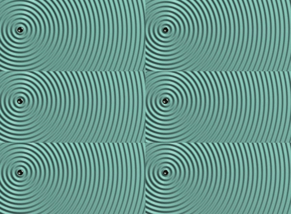 Interaction
of a X-ray front with an
isolated electron, which becomes a new X-ray source, producing the
X-rays waves in a spherical mode
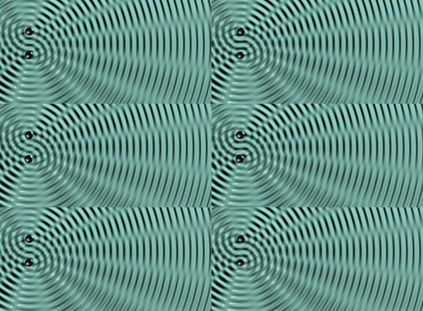 The spherical waves produced by two
electrons interact with each other, producing positive and negative
interferences
Animations
originally taken from physics-animations.com
Ie(Ks)
=
I0 [e4 / R02 m2 c4] [( 1 + cos2 2θ)
/ 2]

Thomson
scattering model
Ks is the scattering vector, R0 is
the distance to the observation point, 2θ
is the angle between the incident direction and the direction where the
scattering is observed; e
and m
are the charge and mass of the electron, respectively, and c
is the speed of propagation of radiation in the vacuum.
 The equation above
describes the Thomson's
model established in 1906 [Joseph
John Thomson (1856-1940)] for the spherical wave elastically
scattered
by a free electron, which is similar to the Rayleigh
scattering with visible light. The scattered wave is
elastic, coherent and spherical. The mass factor (m)
in the denominator justifies neglecting the nuclear
scattering.
The
binding forces between atom and electron are not considered in
the
model. It is assumed that the natural frequencies of vibration
of the electron are much smaller than those of the incident
radiation. In this "normal" scattering model (in contrast to the
anomalous case in which those frequencies are comparable) the scattered
wave is in opposition of phase with the incident radiation.
The second factor (in brackets
equation
above) which depends on the θ angle,
is known as the polarization
factor, because the scattered radiation becomes partially
polarized,
which creates a certain anisotropy in the vibrational directions of the
electron, as well as a reduction in the scattered intensity
(depending of the direction). The scattered intensity shows
symmetry around the incident direction. As the scattered wave
is
spherical, the inverse proportionality to the squared
distance makes the energy per unit of solid
angle a constant.


A solid
angle is the angle in three-dimensional space that an object subtends
at a point. It is a measure of how big that object appears to an
observer looking from that point. Metrically it is the
constant ratio between the intersecting
areas
of concentric spheres with a cone, and the corresponding squared radii
of the
spheres:
A1/R12
= A2/R22 = A3/R32 =
... = solid angle in steradians
The factor of the
geometric "difference of phase"
With
regard to the phenomenon of diffraction and interference, it is
important to consider the phase relationship between two waves due
to their different geometric paths. This affects the difference of
phase α
of the resultant wave:
Φ = 2π(K0.r - ν.t
+ α)
in such a way
that:
α =
2π
(Ks -
K0)
rij
+ α '
where K0
is the wave vector of the incident wave, Ks
is the wave vector in the direction of propagation and rij
is the vector between the two propagation centers which
produces
the phase difference.
If we have several disturbance
centers whose phase differences are measured from a common origin, and
we consider the position vectors rj
of their phase differences, the phase difference of one of the centers
can
be written (using unit vectors in the directions of
propagation with λK
= s)
as:
αj
=
2
π
[(
s
-
s0)
/
λ]
rj
+
α
'
This means that all rj
points in which the product (s - s0) rj has a
constant value (cte)
, will have the same phase, given by:
Scattering by an atom
An atom that can be considered as a
set of Z
electrons (its atomic number) can be expected to scatter Z
times that which an electron does. But the distances between the
electrons of
an atom are of the order of the X-rays wavelength, and therefore we can
also expect some type of partial
destructive interferences among the scattered waves. In
fact, an atom scatters Z
times (what an electron does) only in the direction of the incident
beam,
decreasing with the increasing of the θ angle
(the angle between the incident radiation and the direction where we
measure the scattering). And the more diffuse the electronic
distribution of electrons around the nucleus, the greater the
reduction.
 Phase relationships among the electrons
in an atom

Diagram showing the variation of
the amplitudes scattered by
an electron, without considering the polarization (left figure), and an
atom (right figure). The amplitude (intensity) scattered by an atom
decreases with
increasing scattering angle.

The intensity of the X-rays scattered by
the electrons of an atom decreases with increasing scattering angle
Scheme
taken from School of
Crystallography (Birkbeck
College, Univ. of London)
The atomic
scattering factor is the ratio between the
amplitude scattered by an atom and a single electron. As the speed of
electrons in the atom is much greater than the variation of the
electric vector of the wave, the incident radiation only "sees" an
average electronic cloud, which is characterized by an electron density
of charge ρ(r). If
this distribution is considered spherically symmetric, it will just
depend on the distance to the nucleus, so that, with:
H
= 2 sin θ
/ λ
(which is the length of the scattering vector H
= Ks- K0
= (s
- s0) / λ):
f(H)
= 4π∫(0
→ ∞) r2 ρ(r)
(sin H
r
/ H
r)
dr
Thus, the atomic scattering factor
will
represent a number of electrons (the effective number of electrons of a
particular atom type) that scatter in phase in that
direction, so that θ
=
0 and
f(0)
= Z. The hypothesis of isotropy, ie that this
atomic factor does not depend on the direction of H,
appears to be unsuitable for transition momentum in which d or f orbitals are
involved, nor for the valence electrons.
By quantum-mechanics calculations we
can
obtain the values for the atomic scattering factors, and we can derive
analytical estimates of the type:
f(H) = Σ(1 → 4)
ai
exp
[ -bi
H2 ] + c


Left:
Atomic
scattering factors calculated for
several ions with the same number of electrons as Ne. One can observe
that the O--
has a more diffuse electronic cloud than
Si 4+ and
thus it shows a faster
decay
Right:
Atomic
scattering factors calculated for
atoms and ions with different numbers of electrons. Note that the
single electron of the hydrogen atom (H) scatters very little as
compared with
other elements, especially with increasing Θ.
Hydrogen will therefore be "difficult
to see"
among other dispersion effects
When the frequency of the
incident
radiation is close to the natural vibration of the electron linked to
the atom, we have to make some corrections (Δ)
due to the phase differences that occur between the individual waves
scattered by electrons, whose vibration (due to the incident wave) is
affected by that linking. Thus:
f
(H) = f
0
+ Δ'
f + i Δ''
f
also written
as:
f(H)
= f0
+
f '
+ i f ''
where
f0
is the atomic scattering factor without ligation, as previously
defined, and
i
is the imaginary unit that represents the phase differences between
individual scattered waves. This situation occurs for atoms with large
atomic numbers (heavy atoms), or with atomic numbers close (but
smaller) to the metal atoms in the X-ray anode.
These
corrections, that will be discussed in another chapter,
weakly depend on the
θ
angle, so that this anomalous effect is better
seen at larger values of this angle, although this is where the
scattered beams have lower intensity due to thermal effects
(see below).
[These corrections allow us to
distinguish the chirality
(Bijvoet, 1951) of the crystals and provide us a method
for solving the structure of molecules (SAD,
MAD)].
Due to the movement of the atomic thermal vibrations within
the material, the effective volume of the atom appears larger, leading
to an exponential decrease of the scattering power, characterized by a
coefficient
B
(initially isotropic) in the Debye-Waller (1913, 1923) exponential
factor:
f(H) exp
[ -Biso sin2θ
/ λ2
]
B is 8π2<u2>, <u2> being the quadratic average
amplitude of thermal vibration in the H direction. In the isotropic
model of vibration, B is
considered to be identical in all directions (with normal values
between 3 and 6 Angstroms2 in crystals of organic compounds). In
the
anisotropic model, B
is considered to follow an ellipsoidal vibration model.
Unfortunately, these thermal parameters may reflect not only thermal
vibration, as they are affected by other factors such as atomic static
disorder, absorption, wrong scattering factors, etc.
 Decrease of the atomic scattering factor
due to the thermal vibration
Scattering by a set of
atoms
X-rays scattered by a
set atoms produce
X-ray radiation in all directions, leading to interferences due to the
coherent phase differences between the interatomic vectors that
describe the relative position of atoms. In a molecule or in an
aggregate of atoms, this effect is known as the effect
of internal interference, while we refer to an external
interference as
the effect that occurs between
molecules or aggregates. The scattering diagrams below show the
relative intensity of each of these effects:

Scattering diagrams of a monoatomic
material in different states. In the intensity axis we have neglected
the background
contribution. The figures mainly represent the effect
of the external interference,
while the internal
interference (in this case due to a single atom only) is
simply reflected by the relative intensity of the maxima. Note how the
thermal movement in the
liquid softens and reduces the scattering profile, and how the
maxima produced by the glass also decrease. In the crystal, where the
phase relations
are fixed and
repetitive, the scattering profile becomes sharp with well
defined peaks, whereas in the other diagrams the peaks are broad and
somewhat continuous. In the crystal case the scattering effect
is known as diffraction. Note how the scattering
phenomenon reflects the
internal order
of the sample -- the positional correlations between
atoms.
In the case of
monoatomic gases, the
effects of interference between atoms m
and n
lead (in terms of the intensity scattered by an electron) to:
I(H)
= Ie(H) ΣmΣn
fm(H) fn(H) exp
[2πi
(s - s0)
rm,n
/ λ]
which, when averaged over
the
duration of the experiment and in all k
directions of space, gives rise to the Debye
formula:
<I
(H)>
= I
e(H) ΣmΣn
f
m(H) f
n(H) [ sin 2π|
H|
|r
m,n|
/
2π|
H|
|r
m,n|
]
 Geometry of the scattering produced by a
set of identical atoms
In the case of monoatomic liquids
some
effects appear at short distances, due to correlations between atomic
positions. If the density of atoms per unit of volume (at a
distance r from
any atom with spherical symmetry) is, on average, ρ(r),
then the expression 4π r2ρ(r)
is known as the radial
distribution, and
the Debye
formula becomes:
<I(H)>
= Ie(H) N f2(H)
[ 1
+ ∫(0 → ∞)
4πr2ρ(r)
sin
(2π|H|
|r|) / 2π|H|
|r|
dr ]
All these relationships allow the
analysis of the X-ray scattering in amorphous, glassy, liquid
and gaseous samples.
No
matter the possible complexity with which the phenomenon of X-ray
scattering is presented. The nonspecialist reader should only remember
some simple ideas that are outlined below (drawings taken from
the lecture
by Stephen Curry)...
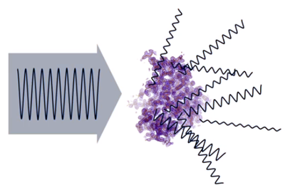
- X-rays are
scattered
by electrons contained in atoms. This dispersion effect (which
is
produced in the form of waves, scattered in all directions of space)
contains different intensities (amplitudes), depending on the number of
electrons (electron density) contributing to the scattered waves...
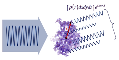
- Taking an
origin in the atomic set
and considering a given direction of dispersion, each of the waves
scattered in that direction can be represented by a mathematical
function (shown in the figure), whose amplitude depends on the
electron density ρ(r)
existing at the point where the wave arises. S
is a magnitude which depends on the angle at which the scattering
occurs.
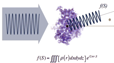
- The total
scattered wave in each direction is the sum of all the individual waves
which scatter in the same direction, f (S).
Its intensity (amplitude) will be governed by the phase relationship
between the contributing waves, which depends on r
(the distance between the points where they originate). This will
happen for all space directions...
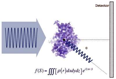
- If
we place a detector (such as a photographic plate) to observe the
scattered waves, f(S),
we obtain a distribution of intensities as shown in the image below...
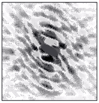
- This "map" of
scattered waves
(shape and intensities) contains information on the distribution of
atoms that are producing the scattering. Mathematically this map is
represented by the function f(S),
which is the Fourier
transform of the atomic distribution, that is, of the
electron
density function…
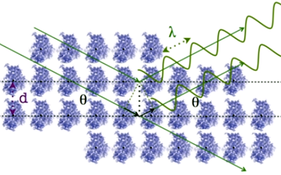
- We will see
later that when the
set of atoms are
arranged in an orderly fashion, ie, in the form of a
crystal, they
behave as a very effective dispersion amplifier...
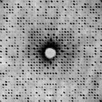
- In these
circumstances,
scattering effects concentrate in certain areas of the detector, very
well defined and regularly distributed, known as diffraction... The
diffraction allows us to obtain an information about the electronic
distribution much richer than the one produced by the
scattering of a
set of disordered atoms...
Scattering by a monoatomic
lattice: Diffraction
When the set of atoms is
structured as a regular three-dimensional lattice (so that the atoms
are nodes of the lattice), the precise geometric relationships between
the atoms give rise to particular phase differences. In these cases,
cooperative effects occur and the sample acts as
a three-dimensional diffraction grid. Under these conditions,
the effects of external
interference produce a
scattering structured in terms of peaks with maximum
intensity which can be described in terms of another lattice (reciprocal
of the atomic lattice) which shows typical patterns,
such as those you can see when you look at a streetlight through
an umbrella or a curtain.

Schematic
diagram of
diffraction patterns
from several two-dimensional point distributions. The parameters of
repetition in the diffraction patterns (reciprocal
space) carry the *
superscript and k
means
a constant scale factor which depends on the
experiment. All
points of
the diffraction pattern have the same intensity, because it is assumed
that the used wavelength is much larger than the points of
the direct lattice (see above in the paragraph about
scattering by an atom).

Relationship
between two
2-dimensional lattices, direct lattice (on the left) and
reciprocal lattice (on the right). The repetition
parameters in reciprocal space carry the *
superscript and k
is a scale factor that depends on the
experiment.
d10
and d01
are the corresponding direct lattice
spacings. Note that the figures show a direct unit cell and a
reciprocal unit cell only, corresponding to the diffraction patterns
shown on the left side of the page. See also direct and reciprocal lattices.
Structured in a lattice, any atom
can be
defined by a vector, referred to a common origin:
R
j,m1,m2,m3
= m1 a
+ m2 b
+ m3 c
where Rj
represents the position of the j node in
the lattice; m1,
m2,
m3,
are integers and a,
b
and
c
are the vectors defining the lattice. According to this,
the intensity scattered by a material would be:
I(H)
= Ie(H) Σm1Σm'1Σm2Σm'2Σm3Σm'3
fj(H)
fj'(H)
exp [2πi
(s - s0)
rm,m'
/ λ]
where:
rm,m'
= Rm1,m2,m3 - Rm'1,m'2,m'3
=
(m1-m'1)
a
+ (m2 - m'2) b
+ (m3 - m'3) c
And calculating this sum we have:
I(H)
= Ie(H)
[ [ sin2 π(s
- s0)
M1 a
/ λ ]
/ [sin2 π(s
- s0)
a
/ λ ] ]
.
[
[ sin2 π(s
- s0)
M2 b
/ λ
]
/ [sin2 π(s
- s0)
b
/ λ ] ]
.
[ [ sin2 π(s
- s0)
M3 c
/ λ ]
/ [sin2 π(s
- s0)
c
/ λ ] ]
= I
e(H)
I
L(H)
In this expression, M1,
M2,
M3
represent the number of unit cells contained in the
crystal along the a,
b
and c
directions, respectively, so that in the total sample the
number of unit cells would be M
=
M1.M2.M3
(around 1015 in crystals of an
average thickness of 0.5 mm).
IL(H)
is the factor of external interference due to
the monoatomic lattice. It consists of several products of
type (sin2
Cx) / sin2
x, where C
is a very large number. This function is almost zero for all x
values, except in those points where x
is an integer multiple of π,
where it takes its maximum value of C2.
The total value would be a maximum value only when all three
products are other than zero, where it will take the
value of M2.
That is, the diffraction diagram of the direct lattice is another
lattice that takes non-zero values in its nodes and that, due to
the Ie(H)
factor, varies from one place to another...
Due to the finite size of the
samples,
the small chromatic differences of the incident radiation, the mosaic
of the sample, etc., the maxima show some type of spreading
around them. Therefore, in order to set the experimental conditions for
measurement, one needs a small sample oscillation around the
maximum position (rocking)
to integrate all these effects and to collect the total scattered
energy.

Graphical representation of one of the
products of the IL(H) function between two consecutive maxima.
Note the transformation from scattering
to diffraction, that
is, from broad to very sharp peaks, as the number of cells M1
increases.
The maxima are proportional to M12
and the first
minimum appears closer to the maximum with increasing M1.
Diffraction
by a crystal
When
the material is not structured in terms of a monoatomic lattice, but
is formed by a group of atoms of the same or of different types, the
position of every atom with respect to a common origin is given by:
R
j,m1,m2,m3
=
m1 a
+ m2 b
+ m3 c
+ rj
= Tm1,m2,m3
+ rj

Reduction inside a unit cell of
the absolute position of an atom through lattice translations
that is, that to go from the origin
to the atom, at position R,
we first go, through the T
translation, to the unit cell origin, and from there with the
vector r
we reach the atom.
As the atom is always
included within a unit
cell, its coordinates referred to the cell are smaller than
the
axes, and often are expressed as fractions of them:
r
= X a
+ Y b + Z c = X/a a
+ Y/b b + Z/c c
= x a + y b + z c
where x,
y,
z,
as fractions of axes, are now between -1
and +1.
Then,
under the conditions initially raised, ie with a monochromatic and
depolarised X-ray beam (as a plane wave, formed by parallel rays of a
common front wave), perpendicular to the propagation unit
vector s0
that completely covers the sample, the kinematic model of interaction
indicates that the sample produces diffracted beams in
the direction s
with an intensity given by:
I(H)
= Ie(H) IF(H)
IL(H)
where Ie
is the intensity scattered by an electron, IL
is the external interference effect due to the
three-dimensional lattice structure, and IF
is the square of the so-called structure
factor,
a magnitude which takes into account the effect of all
internal
interferences due to the geometric phase relationships between
all
atoms contained in the unit cell. This internal structural effect is:
IF(H)
= | F2(H)
| = F(H)
F*(H)
As
a consequence of the complex
representation of
waves, mentioned at the beginning, the square of a complex magnitude is
obtained by multiplying the complex by its conjugate. Thus,
specifically, we give the name structure
factor, F(H),
to the resultant wave from all scattered waves produced by
all atoms in a given direction :
F(H)
= Σ(1 → n)
fj(H) exp
[2π(s
- s0)
rj
/ λ]
As already stated, the phase
differences due to geometric distances R
are proportional to (s
-
s0)
R
/ λ.
This means that if we change the origin, the phase differences will be
produced according to the geometric changes, in such a way that as the
exponential parts of the intensity functions are conjugate complexes,
they will affect the intensities in terms of a proportionality constant
only. Thus, a change of origin is not relevant to the phenomenon.
In the equation of the total
intensity, I(H),
the conditions to get a maximum lead to the following consequences:
- The phenomenon of diffraction in crystal samples is
discrete, spectral.
- The directions and the periodic repetitions in the
reciprocal lattice do not depend on the structure factors.
They only
depend on
the direct lattice. The knowledge of these directions give us the shape
and size of the direct unit cell, which actually controls the positions
of the diffraction maxima.
- The intensity of the diffraction maxima depends on
the
structure factor in this direction (at that reciprocal point), which
only depend on the atomic distribution within the unit cell. In other
words, the diffraction intensities are only controlled by the atomic
distribution within the cell. Thus, through the intensities we can
obtain information about the atomic structure within the unit cell.
- The total diffraction pattern is the consequence
of the
diffraction of the different atomic aggregates within the unit cell,
sampled in the diffraction points produced by the crystal
lattice
(the reciprocal points).
- In summary, structural
crystallography by X-ray diffraction
consists of measuring the intensities of the largest possible amount of
diffracted beams in the 3-dimensional diffraction pattern, to get from
them the amplitudes of the structure factors, and from these
values
(through some procedure to allocate the phases for each of these
structure factors) to build the electronic distribution in the
elementary cell (which can be described in terms of a function whose
maxima will give us the atomic positions).

Diffraction
patterns of: (a)
a single
molecule, (b)
two molecules, (c)
four
molecules, (d)
a periodically distributed linear array of molecules, (e)
two linear arrays of molecules, and (f) a
two-dimensional lattice of molecules.
Note how the pattern of the latter is the pattern of the
molecule sampled in the reciprocal points.
To clarify what has been said above,
the reader can analyze further objects and their
corresponding diffraction patterns through this link.
Additionally we suggest you to watch the video prepared by the Royal Institution to
demonstrate optically the basis
of diffraction using a wire coil (representing a molecule) and a laser
(representing an X-ray beam).
Laue equations,
Bragg's interpretation and Ewald's geometric diffraction
model
We have seen that the diffraction
diagram of a direct lattice defined by three translations, a,
b
and c,
can be expressed in terms of another lattice (the reciprocal lattice)
with its reciprocal translations:
a*,
b*
and
c*,
and these translation vectors (direct and reciprocal) meet the
conditions of reciprocity:
a
a* = b b*
= c c*
=
1 and
a b*
= a c* =
b c* = 0
and they also meet that (for
instance):
a*
= (b x
c)
/ V
(x means vectorial or cross product)
where
V
is the volume of the direct unit cell defined by the 3 vectors of the
direct cell, and therefore:
a*
= N100
/ d100
where N100
is a unit vector perpendicular to the planes of indices
h=1,
k=0,
l=0,
and where
d100
is the corresponding interplanar spacing. And similarly with b*
and c*.
In this way,
any vector in the reciprocal lattice will be given by:
H*hkl
= h a*
+ k b*
+ l c*
= Nhkl
/ dhkl
in
such a way that:
|H*hkl|
dhkl
= 1
 On
the other hand, we have seen that
the maxima
in the diffraction diagram of a crystal correspond to the maximum
function IL(H),
meaning that each of the products that define this function must be
individually different from zero, as a sufficient condition to
obtain a maximum for the diffracted intensity. If we remember
that
H
= (s
- s0) /
λ, this also means
that the three so-called Laue
equations must be fulfilled [Max
von Laue (1879-1960)]:
H
a
= h,
H b
=
k, H c = l
where h, k, l
are integers
Laue equations
There is also
a less formal way to derive and/or to understand the Laue equations,
and
therefore we
invite interested readers to visit this link ...
These three Laue conditions are
met if
the vector H
represents a vector of the reciprocal lattice, so that:
H
= h a* + k
b*
+ l c*
since due to the properties of
the reciprocal lattice, it can be stated that:
Hhkl
a =
h,
Hhkl
b
= k,
Hhkl
c
=
l
Said in other
words: the three conditions of
Laue
(Nobel Prize for Physics in 1914) are sufficient to establish
that the vector
H
is a vector of the reciprocal lattice (
H
=H*hkl).
If these three conditions are fulfilled, and taking into account some
relationships explained above, we can write:
| H
| = 2 sin θhkl
/ λ = | (s
- s0)
|
/ λ =
| H*hkl
|
= 1
/ dhkl
But taking into account that
geometrically we can consider spacings of type dhkl/2,
dhkl/3,
and in general dhkl/n
(ie, dnh,nk,nl,
where n is
an integer), the Bragg’s
equation (Nobel Prize in Physics in 1915 )
would be in the form:
λ =
2 (dhkl /n)
sin θnh,nk,nl
that is:
n
λ =
2 dhkl
sin θnh,nk,nl
where n is
an integer number
Bragg's Law
There
is also
a
less formal way to derive and/or to understand Bragg's Law, and
therefore we
invite interested readers to visit this link...
Moreover,
if the Laue conditions are fulfilled (as explained in
the
following figure) all atoms located on the sequence
of planes
parallel to the one with indices hkl at
a given
distance (DP)
from the origin (DP
being an integer multiple of dhkl)
will diffract in phase, and their geometric difference-of-phase factor
will be:
(s
- s0)
r
= n λ
and consequently a diffraction
maximum
will be produced in the direction:
s
= s0
+ λ
H*hkl

Geometrical model to interpret
the diffraction (in phase) of all parallel planes with indices hkl and
a constant interplanar spacing dhkl,
when the Laue conditions (or their
equivalent, Bragg's Law) are fulfilled. Nhkl is the unit vector perpendicular to the hkl
planes,
and in the diffraction conditions is given by:
The plane equation can, therefore, be
written as:
H*hkl
r
= H*hkl
ri=
|H*hkl|
|ri|
cos (H*hkl
, ri)
= (1/dhkl) DP = n
Moreover, this equation holds all
the
traditional relations of reciprocity of diffraction, between spacing-direction
or position-momentum:
the shorter spacing, the larger angle and vice versa; direct lattices
with large unit cells produce very close diffracted beams, and vice
versa.

The
figure geometrically describes the direction of the diffraction beam
due to the constructive interference between atoms located on
the
planes with interplanar spacing d(hkl).

The
figure depicts a description of Bragg's model
when different
types of atoms are located on their respective parallel planes with Δd spacing.
The separation between blue and green planes creates interferences and
differences of phases (between the reflected beams) giving
rise to
changes in intensity (depending of the direction). These intensity
changes allow us to get information on the structure of atoms
that
form the crystal).
Readers with installed Java Runtime
tools can play with Bragg's model using this
applet.
On the other hand, we have seen
that, in
general:
H
= (s - s0)
/ λ
= -s0/λ
+ s/λ
and
this means that the vectors H can be considered as belonging to a
sphere of radius 1/λ centered at a point defined by the
vector -s0/λ with respect to the origin where the
crystal
is. This is known as Ewald's
sphere (Ewald,
1921), which provides a very easy geometric interpretation of the
directions of the diffracted beams. When the H vectors
belong to the reciprocal lattice and the end of the vector (a
reciprocal point) lies on that spherical surface, diffracted beams are
produced, and obviously the crystal planes are in Bragg's position.
 It's
amazing how quickly Paul Peter Ewald
(1888-1985) developed this interpretation only some
months after Max
von Laue experiments. His original article, published in 1913
(in German), is available through
this link. The
advanced reader can also consult the article published by Ewald in Acta
Crystallographica (1969) A25, 103-108.
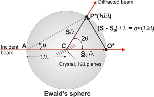
This
figure describes Ewald's
geometric model. When a reciprocal point , P*(hkl),
touches the surface of Ewald's sphere, a diffracted beam is
produced starting in the centre of the sphere and passing
through
the point P*(hkl). Actually the origin of the reciprocal
lattice, O*,
coincides with the position of the crystal and the diffracted beam will
start from this common origin, but being parallel to the one drawn in
this figure, exactly as it is depicted in the figure below.

This
figure shows the whole reciprocal volume that can give rise to
diffracted beams when the sample rotates. Changing the orientation of
the reciprocal lattice, one can collect all the beams corresponding to
the reciprocal points contained in a sphere of radius 2/λ
known as the limit sphere.
Reciprocal points are shown as small gray spheres .
To obtain all possible diffracted
beams
that a sample can provide, using a radiation of wavelength λ,
it is sufficient to conveniently orient the crystal and make
it
turn,
so that its reciprocal points will have the opportunity to
lay on
the surface of Ewald's sphere. In these
circumstances, diffracted beams will originate as described
above. With larger wavelengths, the volume of the reciprocal space that
can be explored will be smaller, but the diffracted beams will appear
more separated.

Ewald's
model showing how
diffraction
occurs. The incident X-ray beam, with wavelength
λ, shown
as a white line, "creates" an
imaginary Ewald's sphere of diameter
2/λ
(shown in
green).
The reciprocal lattice (
red
points) rotate as the crystal rotates, and
every time that a reciprocal point cuts the sphere surface a diffracted
beam is produced from the center of the sphere (yellow arrows).
 Ewald
model, identical to the one shown in the upper figure, but in two
dimensions, and showing the detector where the diffracted beams are
collected
Taken from Philip Willmott (Paul Scherrer Institute, Switzerland)
This
Java application can be downloaded from this link.
It is totally virus free, and based on the concept of the reciprocal
lattice. It allows
playing with the Ewald's model to understand the diffraction. Original
by Nicolas Schoeni and Gervais Chapuis of the Ecole
Polytechnique
Fédéral de Lausanne (Switzerland).
According
to Bragg's
Law, the maximum angle at which one can observe
diffraction will correspond to the angle where the sin function is
maximum (=1). This also means that the theoretical
maximum resolution
that can be achieved is λ/2. In
practice, due to the decrease of the atomic scattering factors by
increasing Bragg angles, appreciable intensities
will appear only up to a maximum angular value of θmax
< 90º
and the real
maximum resolution reached
will be dmin
= λ/2
sin θmax.
Considering that the
interplanar spacings dhkl
are a characteristic of the sample, by reducing
the wavelength, Bragg's Law indicates that the diffraction
angles (θ) will decrease; the spectrum shrinks,
but on the other
hand, more diffraction data will be obtained, and therefore a better
structural resolution will be achieved.

According
to Ewald's model, the
amount of reciprocal space to be measured can be increased by
reducing the wavelength, that is, by increasing the radius of the
Ewald's sphere
It is also very helpful to visit
the pages that on reciprocal
space are offered by the University
of Cambridge through this link, as well as to look at
the video made by www.PhysicsReimagined.com,
showing the geometric relationships between direct and reciprocal
lattices, displayed below as an animated gif:
Once
the foundations of the theoretical model which describe the phenomenon
of diffraction are set, we encourage the reader to visit the pages
dedicated to the different experimental methods to measure the
diffraction intensities.


